NES ROMs
Created: 2020-03-04 21:33:36 -0800 Modified: 2020-03-11 16:30:33 -0700
Resources
Section titled “Resources”Zorchenhimer shared a bunch of resources with me before I even started “officially” learning, so I’ll include them all here:
- Things to download
- Assembler and linker: cc65 suite
- NES emulator: Mesen
- My notes on Mesen are here.
- Graphics editor: YY-CHR
- Visual Studio Code plugin for CC65
- The default keybindings for this are atrocious
- References
- NesDev Wiki - Everything you’ll ever need to know about NES hardware
- Assembler and linker command documentation
- ca65 documentation specifically (opcodes, addressing modes, etc.)
- An in-depth NES tutorial
- FamiTracker for making music
- Zorchenhimer’s modified assembly documentation
- ↑ Appendixes of that resource
- Searching for something like “CMP oper” is better than just searching for “CMP” due to how many times these terms appear
- ↑ Appendixes of that resource
Extra references that someone other than Zorchenhimer gave me:
- Resources about 6502 processor and assembly
- Cheat sheet of opcodes
- A great blog post on how Zelda does its scrolling effects
Terminology/reference (reference)
Section titled “Terminology/reference (reference)”- NMI: non-maskable interrupt
- DMA: direct memory access. From what I understand, this typically refers to the ability to write into CPU RAM and have it update the PPU’s OAM (reference) since normally the CPU has no access to PPU RAM. Normally, the CPU communicates with the PPU through the PPU’s registers. If you think about this in terms of a programming interface, the PPU only exposes roughly 10 “functions” through its registers.
- Blanking
- Horizontal blanking: the time between individual horizontal scanlines where the CRT TV’s electron beam has to move back to the beginning of the next row. This is generally very short.
- Vertical blanking (AKA “vblank”): the time after rendering all scanlines on the screen where the electron beam has to move back to the beginning of the first scanline. This is like a slightly longer horizontal blank from what I understand.
- OAM: object attribute memory. This is internal memory in the PPU that can contain up to 64 sprites (since each sprite is 4 bytes and a page is 256 bytes).
- Mapper: colloquially, it sounds like a mapper is any extra chips/hardware that may be in the cartridge itself in order to extend the capabilities of the game (e.g. adding RAM, extra sound channels, etc.). Technically though, I believe the mapper is everything in the cartridge based on what it says here: “NROM: About the simplest mapper there is; 32K PRG and 8K CHR. Most beginners start with this.”
- PPU: picture processing unit.
- APU: audio processing unit.
- PRG ROM: essentially the code and data for a game. This was a physical chip in the cartridge.
- CHR ROM: essentially the graphics/sprites available to the PPU. This was a physical chip in the cartridge.
- NROM: pretty much just a basic cartridge. Doesn’t use memory mapping, just has PRG ROM, CHR ROM, and a CIC.
- MMC1: the memory management controller chip. This was a physical chip in a cartridge that would support saved games and multi-directional scrolling.
- CIC: Checking Integrated Circuit - a physical chip in the cartridge that was like DRM (except that it was easily thwarted).
Basics
Section titled “Basics”-
The NES uses stack-based processing. It’s an 8-bit architecture with 16-bit addressable space (65536 bytes). Mappers could provide access to more memory.
-
The NES renders 32x30 tiles (256x240 pixels).
-
The NES runs on modified 6502. The biggest modification is that there’s no decimal mode.
-
All text must be rendered by sprites. ASCII characters need to be at the same offsets in CHR ROM.
-
There are three main parts of a ROM file: a 16-byte header, the PRG data, and the CHR data.
-
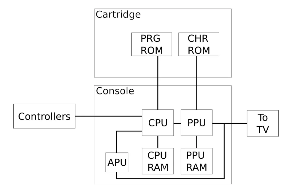
This diagram shows how everything is connected
-
Numerical references
- Hex reminders:
- 0x10 = 16
- 0x100 = 256
- 0x1000 = 4096
- This means that “$2000” in terms of bytes is 8KB.
- A “word” is two bytes
- A page is 256 bytes
- Hex reminders:
-
Byte order in the PPU is big-endian (reference)
-
Different TVs ran at different framerates, so the NES would run at either 50 FPS or 60 FPS, which meant that you had to be careful about what you tied to a framecount or else gameplay (and potentially even audio) could be faster/slower than you intended.
-
The general code flow is:
- Initialize everything
- Go into frame code (handle collisions, handle input, etc.)
- Handle NMIs triggered from the PPU. This is where we transfer data to the PPU and potentially the APU to keep audio in sync with the visuals.
Memory layout
Section titled “Memory layout”- The “zero page” is the fastest RAM to use as a consequence of it being the first page (which is 256 bytes), meaning you only need one byte to point to any part of that memory.
- The page after the zero page is the hardware stack. It grows from 0x1FF downward to 0x100, meaning it’s only 256 bytes large.
- After the stack is slightly less than 2 KB of memory, which is our main memory for level data, audio data, etc.
- After that, two separate regions of memory-mapped IO to talk to the rest of the system, e.g. communicating with the PPU or APU.
- There are two square channels, a triangle channel, and a noise channel.
- There’s also a DMC (delta modulation channel) which takes a lot of processing. It’s used for low bitrate sound clips, e.g. voice clips.
- If you turn a sound on, it’ll be on until you turn it off. This means that you may want to make your music programmatic so that you can save space.
- The PPU RAM has nametables which is the index into the CHR ROM.
- Palettes: 8 total palettes (4 for BG, 4 for sprites)
- Each palettes has 3 primary colors and one background color
- For sprites, the background color is considered the transparent color
- There’s the background layer, which is a special property of the PPU. It WILL render its background palette color.
- The background layer is in a grid, so you can only put things at precise offsets
- Sprite 0 (keyword: “sprite zero”) is special. It’s the only one we can see if it’s drawn yet since we can check if a non-background pixel of the sprite rendered on a non-background pixel of the background
- Remember: non-background pixels of the sprite are transparent, so they’re unimportant. For the background, background pixels are just a solid color to render.
- When setting PPUCTRL (http://wiki.nesdev.com/w/index.php/PPU_registers#PPUCTRL), you can change Increment Mode, which will switch from rendering horizontally (+1 tile for each draw call) or vertically (+30 since there are 30 tiles per column). This is the PPU’s internal RAM address, which is NOT what you see in $2006 on the CPU (http://wiki.nesdev.com/w/index.php/PPU_registers#PPUADDR)
- OAM (object attribute memory) - dedicated sprite memory in the PPU
- PPU can communicate directly with the CPU, CHR ROM, and PPU RAM, but doing anything through the CPU is going to be a bit slower than the others.
- Color emphasis is frequently used on pause screens to dim the colors in the background.
- 64 8x8 sprites available - can have that many on the screen at the same time, but not all at the same scanline
- Only 8 per scanline. This is what causes the flickering that you see on NES games. You can sort of bypass this by rendering sprites as background tiles since they don’t have this same restriction.
- You can also render sprites as 8x16. Zelda rendered 16x16 tiles, meaning they paired up two 8x16 tiles.
- Remember that the 8-per-scanline property makes it so that it doesn’t really matter if you’re rendering 4 8x8 tiles or 2 8x16 since they’ll both have two sprites per scanline.
- To wait for a vblank to happen, you can check the PPU register $2002 (PPUSTATUS):
: BIT $2002 BPL :-Explanation: [12:40] WaielAl: @Adam13531 “BIT 2005/$2006” (These are the register that are writen to twice. As you dont know to which byte (high/low) you will write, you have to reset them first)
Apparently this is only fine to loop on $2002 during warmup (reference).
- Mirroring mode
- PPU only has enough RAM for two nametables, so it can store the tiles for the current screen and one more, so we can choose how to orient those two nametables. The mirroring is either horizontal, meaning anything drawn in quadrant 1 will also be drawn in quadrant 2:
- Quadrants
- PPU only has enough RAM for two nametables, so it can store the tiles for the current screen and one more, so we can choose how to orient those two nametables. The mirroring is either horizontal, meaning anything drawn in quadrant 1 will also be drawn in quadrant 2:
| 1 | 2 |
|---|---|
| 3 | 4 |
-
That means that if you want to be able to move horizontally in your game, you’d have vertical mirroring so that quadrants 1 and 2 can contain different information.
-
You can change the mirroring direction with flag 6 in the INES header (reference)
-
The nametable takes up 1 KB of PPU RAM, but the background tile information is only the first 960 bytes of that. The remaining 64 bytes make up the attribute table (reference).
-
We can only write to the PPU when it’s not already drawing the screen, which is only during a horizontal blank or when we’ve turned off rendering entirely. A horizontal blank is roughly enough time to write maybe 3 bytes. We typically use this for scrolling because that’s something that’s handled entirely through the PPU, so it’s very fast.
- After turning off the PPU, you can update sprites, palettes, scrolling, etc.
-
When rendering sprites or the background, you can choose the address that you’re going to render from. For example:
- The bit that controls whether you’re drawing from the top or the bottom there is in PPUCTRL (reference). E.g. in my RESET code, I have this
; Enable NMI (most significant bit) and set the background pattern table address to $1000LDA #%10010000STA PPUCTRLScrolling (reference)
Section titled “Scrolling (reference)”- Scrolling is accomplished by setting PPU register 2005](https://wiki.nesdev.com/w/index.php/PPU_registers#PPUSCROLL); you call into it twice (X → Y). You have to set it every frame if you're also going to [PPUADDR (2006) (reference), and you should typically do so at the end of each NMI.
- If you want to be able to scroll in both directions, you likely would need a mapper for that since you’d probably want more than two nametables in memory.
- To be able to switch mirroring dynamically, you need bit 6 set in the header (reference). I assume this was used for games like Zelda where you could scroll the whole screen at a time in a single cardinal direction.
OAM example with code
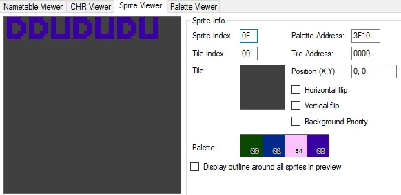
Section titled “OAM example with code”One task I was trying to accomplish as a beginner is to change a single palette color. I looked through Mesen and found this in the PPU Viewer:
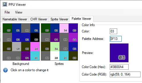
Shown above: I have the upper right sprite color selected, which is color 03.
My goal was to change this to white. Clicking any of the colors shows you the color table where I found that white is $30. The question was then about how I change PPU memory to have that value of 30. This is done via PPU registers since you don’t have direct memory access to the PPU.
- You need two writes into XXYY into
LDA $XXSTA $2006LDA $YYSTA $2006- After that, you can set the value XXYY in the PPU with this:
LDA $ZZSTA $2007The final code that I wrote to update a single color in a palette looks like this:
; Write to $3F13 as shown in the picture above    LDA #$3F    STA $2006    LDA #$13    STA $2006
; Write $30 to $3F13 LDA #$30 STA $2007- Sprites are four bytes:
- First byte: Y position (in pixels, 0-238). Anything after 238 is not drawn because the screen is shorter than it is wide.
- Second byte: tile index number. The CHR viewer shows this; there are 256 tiles at any time.
- Third byte: attributes byte
- Priority: it’s like Z-index on sprites. 0 means “in front of background”, 1 means “behind”. Tiles are drawn in the order that they appear in RAM. Overlapping sprites will act strange if they have different priorities.
- If a sprite is drawn behind the background, then it will draw above the solid background color and below the non-background-colored background pixels
- Horizontal and vertical flipping
- Palette
- Priority: it’s like Z-index on sprites. 0 means “in front of background”, 1 means “behind”. Tiles are drawn in the order that they appear in RAM. Overlapping sprites will act strange if they have different priorities.
- Fourth byte: X position (0-255)
- Remember that you have 64 8x8 sprites, and even if you clear out all of the data, they’ll still render based on how you cleared the data. For example, if you zero out all of the sprite memory, then you’ll be rendering sprite #0 at (0,0) with 0 attributes, which means you’ll have a visible sprite at the upper left.
- You store sprites in OAM in the PPU (reference). This is typically done by mapping a memory segment from the CPU (typically 02FF) as shown below:
;nes_000.cfgMEMORY {    ZP: start = $00, size = $0100, type = rw, file = "";    OAM: start = $0200, size = $0100, type = rw, file = "";    RAM: start = $0300, size = $0500, type = rw, file = "";    HDR: start = $0000, size = $0010, type = ro, file = %O, fill = yes, fillval = $00;
    PRG: start = $8000, size = $4000, type = ro, file = %O, fill = yes, fillval = $FF;    CHR: start = $0000, size = $2000, type = ro, file = %O, fill = yes, fillval = $CC;}
; main.asm; Have the linker reserve a page for us.segment "OAM"sprites: .res 256
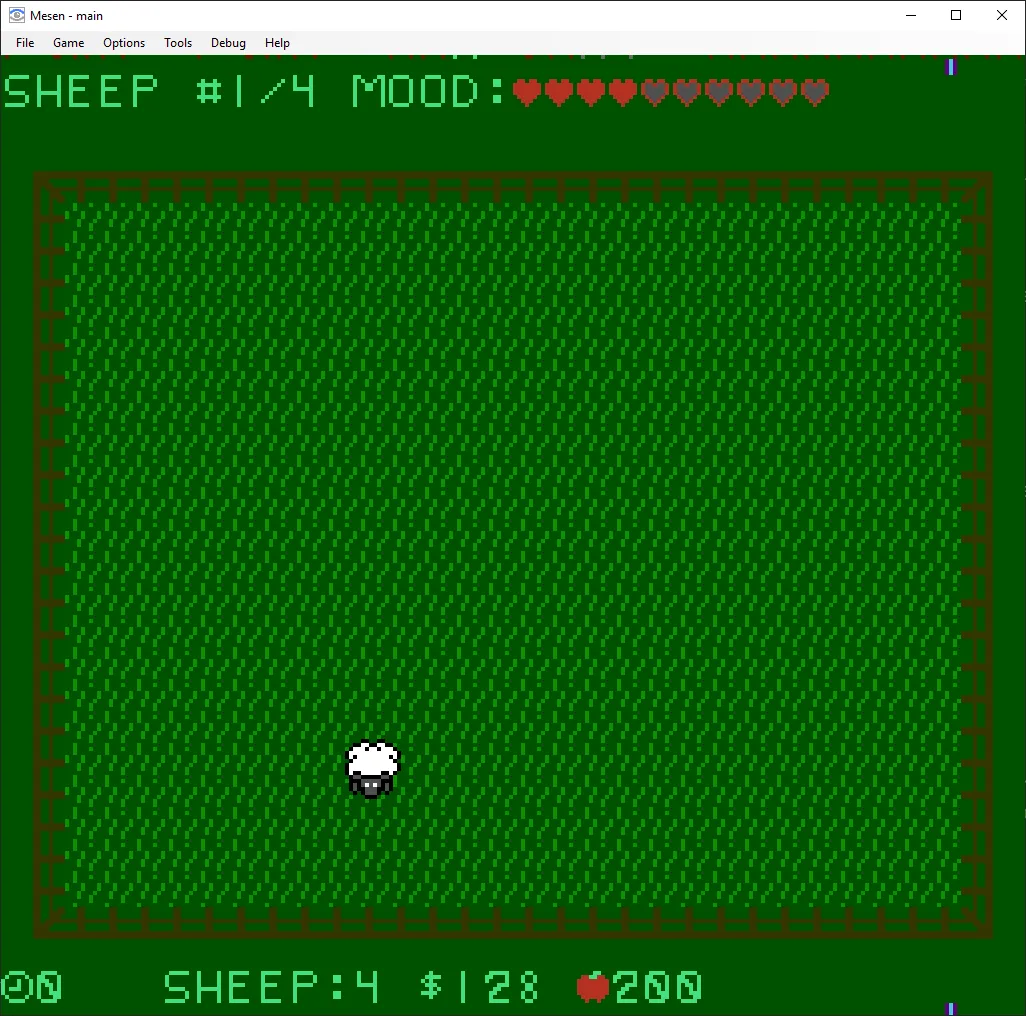
;…later in the file, load a tile into a spriteLDA #$15 ; load tile index 0x15STA sprites+1 ; store it into the first byte↑ Just by doing that code, you’ll see this in the PPU
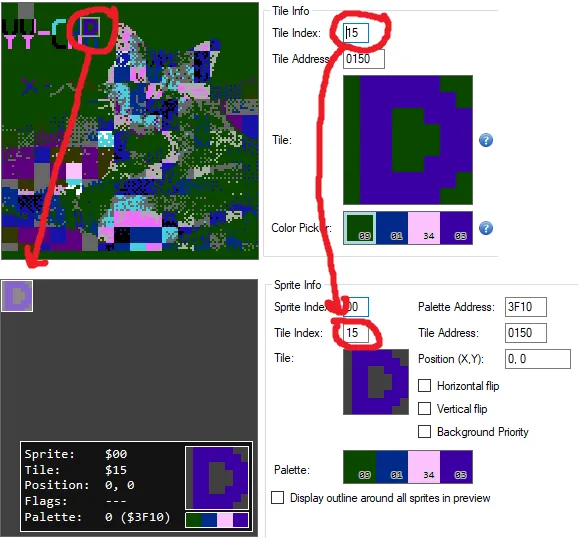
- After setting various values in the “sprites” segment of OAM, you’ll start to see the sprites appear here:
Drawing to the background
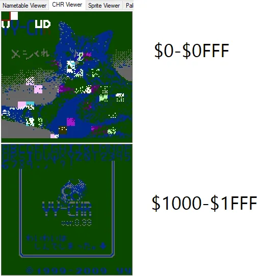
Section titled “Drawing to the background”The background is essentially the nametables, and you only have two at any given time. In fact, my nes_000.cfg says that CHR memory is of size $2000, which is 8 KB. If you look at the PPU viewer
CHR format
Section titled “CHR format”- 2 bits per pixel (since there are four colors), laid out in planes. YYCHR is the program that you would start out using for modifying sprites.
- Here’s a site that lets you drag and drop images and create a .chr from it: https://make.vg/brewtool/chr/index.html
- One tile is 8px by 8px, so 64 pixels. It’s stored in 16 bytes. The first bit of each pixel is in the first eight bytes (the first plane), then the second bit of each pixel is in the second eight bytes.
- The palette information comes from the attribute information in the background. This assigns palettes to different areas of the name table. Attributes have a different resolution from tiles themselves; attribute cells are 32x32 pixels, but tiles are 8x8, meaning there are 16 total tiles per attribute cell. However, the cells themselves are split into 2x2 tile areas. This means that attribute tables have 2 bits per four-tile square representing with palette to use. Here’s a good video for the attribute table.
- Palette information is not in the “TILES” segment in the linker.
The NROM mapper (mapper 000)
Section titled “The NROM mapper (mapper 000)”Zorchenhimer said “this maps the ROMS on the cartridge (PRG and CHR) directly into the CPU”. Here’s a .cfg file for the linker that will specify all of the layouts here:
MEMORY {    ZP: start = $00, size = $0100, type = rw, file = "";    OAM: start = $0200, size = $0100, type = rw, file = "";    RAM: start = $0300, size = $0500, type = rw, file = "";    HDR: start = $0000, size = $0010, type = ro, file = %O, fill = yes, fillval = $00;
    PRG: start = $8000, size = $4000, type = ro, file = %O, fill = yes, fillval = $FF;    CHR: start = $0000, size = $2000, type = ro, file = %O, fill = yes, fillval = $CC;}
SEGMENTS {    ZEROPAGE: load = ZP, type = zp;    OAM: load = OAM, type = bss, align = $100;    BSS: load = RAM, type = bss;    INESHDR: load = HDR, type = ro, align = $10;
    PAGE0: load = PRG, type = ro, start = $8000;    VECTORS: load = PRG, type = ro, start = $BFFA;
    TILES: load = CHR, type = ro, optional = yes;}
Segments will define memory addresses for us in code that the linker will replace, so the names aren’t important (other than the fact that you have to be consistent with them).
- BSS: main RAM
- INESHDR: the 16 bytes for the header of the ROM
- VECTORS: RESET, IRQ, and NMI vectors/pointers
- The very first thing the ROM does when the CPU is turned on is go to the address pointed to by this RESET vector. It’s the same case when the NES is reset. It does not clear the memory though when you reset, so you typically want to clear this out at start-up. Clearing all of the memory takes roughly 2 frames (1/30th of a second total).
- TILES: this is for both background-layer stuff AND sprites
Basics
Section titled “Basics”- Number formats
- $ represents that a number is in hex
- % represents that a number is in binary
- In general, everybody knows either the fewest amount of opcodes to do something or the fastest way to do something, and you typically have to pick which one you want.
- The “.res” directive reserves space in memory that you can point to later (reference). For example, perhaps you want the player’s ability cooldown to be a byte in memory somewhere and not get stomped on by other values; you’d reserve a byte like this:
Player_cooldown: .res 1
- CA65 has a bunch of different directives (reference). One of them is “.include”, which is what lets you split your code into several files. It’s very simple to set up since most assembly files have no concept of “ordering” (they’re just labels and instructions).
- Handling controller/joypad input
- There are 3 main registers: the accumulator (A) and the index registers (X and Y)
- The stack pointer is technically a register, but we don’t really interact with it
- Instructions have a source/destination baked in most of the time (e.g. “LDA” knows that it puts the value into A), so we usually only need to provide one extra piece of information.
- Here’s a reference of all of the official opcodes
- There are also illegal opcodes, but they’re not supported everywhere
- Instructions fit into some basic categories…
- Data movement
- Loading (prefixed with “L”, e.g. “LDA”)
- Saving (prefixed with “S”, e.g. “STA”)
- Transferring (prefixed with “T”, e.g. “TSX”)
- Flow control
- Comparisons (e.g. register to memory location). These all set flags, which you then check.
- Flags
- N: negative
- Set when values END as a negative number
- Z: zero
- C: carry
- I: interrupt (not really used)
- D: decimal mode (not used at all)
- NES implements the flag, but no decimal math
- V: overflow
- Used for arithmetic that goes 127 → -128 or vice versa
- N: negative
- Branches/jumps
- Unconditional jumps
- Conditional jumps (based on flags)
- Subroutines (JSR) to “jump there and come back”. A JSR should be paired with an RTS back to the caller. JSR puts the return address on the stack, and RTS will take it off.
- You can actually manipulate the stack yourself though to have a sort of dynamic jump. If we do that though, we need to make sure we manipulate the stack state again so that we don’t just keep filling it (i.e. make sure to pop off the stack if you manipulate the return addresses).
- Conditionals (like CMP, CPX, CPY). Compares almost always precede branches since they’re just used for setting flags, so if you’re doing that, you want to use the flag afterward.
- RTI / RTS (return from interrupt or subroutine)
- Interrupts (IRQ), e.g. used in memory mappers to count scanlines, DMC for timing
- These can just be outright turned off
- Non-maskable interrupts (NMI) can’t be turned off (unlike IRQs).
- PPU uses it to say that it rendered one full screen and it’s ready to accept data again.
- There aren’t really any system calls like “clear the screen” since you do that by modifying memory directly.
- Data movement
- Math
- All math happens on the accumulator (the A register)
- Two’s complement math (https://en.wikipedia.org/wiki/Two%27s_complement)
- -1 is represented by 0xFF
- Consider signed values to be between -128 to 127
- Remember that in the end, it’s all how you’re interpreting 8 bits, but the above is important for when it comes to flags like carry and overflow.
- Operations are very basic: adding, subtracting, and bit-shifting. Bit-shifting comes in two forms
- Shifting: shifting will discard anything shifted too far. This can read the carry flag.
- Rotate: the value that would have been discarded is moved to the carry bit. This can read/write the carry flag.
- Adding and subtracting can only happen with the carry flag considered (ADC and SBC), but there are different semantics for each due to two’s-complement math. If you don’t want to consider the carry flag for addition, then clear it first via CLC. If you don’t want to consider the carry flag for subtraction, then set it via SEC.
- E.g. adding 10 to whatever number is stored at ADDR looks like this
LDA ADDR ; load the value of ADDR into ACLC ; clear the carry flag in case it was setADC #10 ; add 10Similarly, subtracting 10 from whatever number is stored:
LDA ADDRSECSBC #10- There are no multiplication operators, so people use either “for” loops or look-up tables for multiplication. So multiplying by 3 would be like an array-based group of precomputed products.
How to figure out the hundreds digit of a number (a single byte)
Section titled “How to figure out the hundreds digit of a number (a single byte)”I wanted this code to be able to render a byte as text. This code was not straightforward because there’s no proper division or multiplication, and subtracting numbers with two’s-complement math is strange when it comes to the carry flag. The general algorithm used here is to subtract 100 repeatedly until we’re at a number less than 100.
LDA #255 ; this is the number to figure out the hundreds digit for    LDY #0; this will end up counting what the hundreds digit is, i.e. it's the output of this "function"
@loop:    CMP #100    BCC :+ ; we'll branch if the carry is clear, which means 100 is greater than our number
    ; SEC ← This is implied because the carry is guaranteed to be set at this point    SBC #100    INY ; count up from our hundreds digit    JMP @loop:    RTS
If you want to take fewer cycles at the cost of more bytes of code, you can unroll the loop.
Best practices
Section titled “Best practices”- Labels are free since they don’t add to the ROM size, so split up practically everything you do by label to make it more obvious where blocks of code start and stop.
- Make constants with “FOO = BAR” at the top of some file (probably constants.asm) and refer to those, e.g. for PPU registers so that you don’t type $2002 all the time.
- Function parameters are used quite a lot, so storing them in the zero page is a good idea to save CPU cycles.
- Use the X or Y registers for loop counters since they have INX, INY, DEX, and DEY for incrementing and decrementing. Alternatively, you can use “INC <memory address>” to work directly on memory, but that takes more CPU cycles.
- If you’re in the middle of a function and want to save something off, use the stack (PHA and PLA). It’s 3 cycles to save and 3 to load, but it doesn’t require using extra space in zero-page (which would also be 6 cycles).
”Functions”
Section titled “”Functions””As with most assembly languages, functions don’t really exist; it’s just code at a label and then typically a place to return to. 6502 is no different; you have JMP, JSR, and RTS.
- For functions with a single parameter, you can probably just use one of the three registers (A, X, or Y). Any more than one parameter and you’ll find it difficult to juggle them in just registers.
- If you push a register onto the stack, you’ll find it difficult to use because JSR also pushes to the stack, so if you pop right after a JSR, you’ll get the return address and then mess everything up.
- You can reserve a byte or two in memory and save parameters to addresses as shown below:
; --------------------------------------------------------------------------------; BSS - general variables / main memory; --------------------------------------------------------------------------------.segment "BSS"
; These are just parameters to subroutinesparam1: .res 1param2: .res 1
;…later in the code
LDA #42STA param1 ; store 42 at the address pointed to by param1JSR SOME_SUBROUTINE ; call a subroutine
SOME_SUBROUTINE:LDA param1 ; Load the parameter that we saved; ...code to use the parameter that is now in the A register
RTS ; Return from subroutineRendering text
Section titled “Rendering text”- You would likely store the text directly in your PRG, meaning you could just use a label like this:
HELLO_WORLD:.byte "HELLO WORLD"- You could either keep track of the length of the string or have a null terminator at the end (via .ASCIIZ) so that you know when to stop rendering. If you’re going to keep track of the length, then you could do so with a little bit of magic here:
HELLO_WORLD: .byte "HELLO WORLD"HELLO_WORLD_LENGTH = * - HELLO_WORLDHELLO_WORLD_LENGTH will now be 11. The ”*” is notation for the address that line would have been on. Note that to *use* this value, you need to treat it as an immediate, e.g.
LDA #HELLO_WORLD_LENGTH- Unless you want every single ASCII character, then you’re probably going to want to use .CHARMAP to remap ASCII values to the characters you did include. This does not inflate the resulting ROM at all; it’s like a find/replace on strings at a byte level.
Addressing modes (reference)
Section titled “Addressing modes (reference)”For all of these, the appendix has examples in the second column (“Assembly Language Form”)
- Immediate: just use a numerical constant as identified by the ”#” symbol
- Accumulator: always uses the A register
- Zero page: interacts with the first 256 bytes of memory (0-255)
- Zero page, X: the index mode. We look ahead based on the value in register X.
- Absolute: access any addressable RAM
- Absolute, X or Y: index modes just like the zero-page X, but it uses either register
- “Indirect” is how they do pointers. All pointers must be in the zero-page. If you try doing something like “STA (sprites, X)” where “sprites” points to OAM, then you’ll get “Error: Illegal addressing mode”.
- (Indirect, X): not too many uses. Loads the address where the pointer is, then adds X to the address of the pointer. We may never even use this addressing mode.
- (Indirect), Y: more common than the other form, e.g. to load data to the PPU.
- Indirect (no parentheses): only used for JMP, jumps with no pointer arithmetic
- Relative: only used for branches. It’s two bytes - branch instruction plus the offset. The offsets are signed, so you can only jump to 127 bytes away, so you sometimes need to chain branches/jumps.
To load addresses into a register, you can use this syntax:
- “LDA #<SOME_LABEL” loads the low byte
- “LDA #>SOME_LABEL” loads the high byte
For example, here’s how you’d set a zero-map variable named memory_address_pointer to the address that holds WORLD_MAP:
LDA #<SIMPLE_WORLDMAP ; Load low byte STA memory_address_pointer ; Store low byte LDA #>SIMPLE_WORLDMAP ; Load high byte STA memory_address_pointer+1; Store high byteOptimizations
Section titled “Optimizations”This section contains random optimizations that you can do. As always, don’t prematurely optimize your code since you may introduce bugs or quirks.
- Don’t write code that unnecessarily loads into a register when you can act directly on the address:
- BAD
LDA moneyCMP #0- GOOD
CMP moneyKeep in mind that the “BAD” case isn’t really bad if you need “money” to be in a register afterward.
- Likewise, don’t use CMP when another instruction sets the flag that you want anyway
- BAD
LDA moneyCMP #0BNE @foo- GOOD
LDA money ; this already modifies the "Z" flagBNE @foo- If you have code like this:
SOME_LABEL:JSR FOOJSR BARJSR BAZRTS…then you can convert it to just call into FOO and put the “RTS” at the bottom of “BAZ” and let the code fall through. This will save time on the JSR/RTS combos
Troubleshooting
Section titled “Troubleshooting”Rendering is happening at unexpected scroll coordinates
Section titled “Rendering is happening at unexpected scroll coordinates”Writing to the PPU itself is what changes the scroll coordinates due to a shared internal register, so it doesn’t matter if you’re not explicitly writing to PPUSCROLL. If you see something rendering at the wrong scroll coordinates, then you may have to put your render code into the NMI before the scrolling is done so that you don’t have the wrong order of operations. Remember that the PPU can interrupt the CPU at any point.
Typically, you would buffer changes during the frame draw but not actually write those changes until the NMI.
Alternatively, you may just be trying to do too much during an hblank or a vblank. You can write roughly 3 bytes during an hblank and roughly 64 bytes during a vblank. When you try to do too much, there’s a race condition like what’s shown below:
In general, do as few calculations as possible during the vblank. Ideally, you’d just be pulling state from memory and rendering that as fast as possible, not doing things like random number generation, etc.